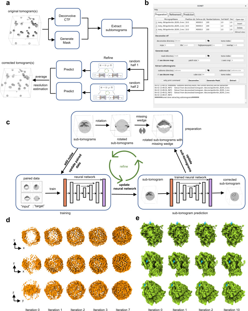
Fig. 1. Principle and workflow of IsoNet.
a Workflow of the IsoNet software. b GUI of IsoNet. c Illustration of Refine step: First, subtomograms are rotated and then applied with additional missing-wedge artifacts along other directions (e.g., YZ axis) to produce paired data for training. Second, the paired data is used to train a neural network with U-net architecture. Third, the trained neural network is applied to the extracted subtomograms to produce missing-wedge corrected subtomograms. The recovered information in these subtomograms is added to the original subtomograms, producing new datasets for the next iteration. d, e Validation of IsoNet with simulated subtomogram of apoferritin (d) and ribosome (e). Surface views from three orthogonal directions of the reconstructions are shown after increasing iterations of IsoNet processing. Blue arrows indicate segments of RNA duplexes.

