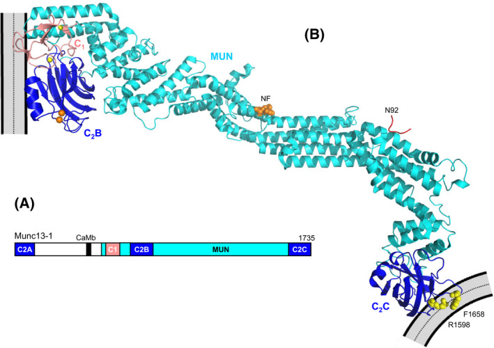
Fig. 8.

Munc13‐1 bridging a synaptic vesicle and the plasma membrane. (A) Domain diagram of Munc13‐1. The length of Munc13‐1 is indicated by the number on the right, above the diagram. (B) Model of how Munc13‐1 bridges a synaptic vesicle and the plasma membrane in an approximately perpendicular orientation. The ribbon diagram represents one of the structures of Munc13C determined by cryo‐EM of 2D crystals of Munc13C between to phospholipid bilayers [177] (PDB accession code 7T7V) by reconstructing the density map with the help of models from AlphaFold [184] and the crystals structure of Munc13‐1 C1C2BMUN [176], Ca2+‐bound Munc13‐1 C2B domain [60] and the MUN domain [25] (PDB accession codes 5UE8, 6NYT and 4Y21, respectively). The C1 domain is shown in salmon and the C2B and C2C domains in blue. Ca2+‐ions bound to the C2B domain and zinc ions bound to the C1 domain are shown orange and yellow spheres, respectively. Residues N1128 and F1131 (NF), which are critical for the activity of the MUN domain in opening syntaxin‐1 [25], are shown as orange spheres, and R1598 and F1658 in the loops of the C2C domain, which are crucial for the membrane bridging activity of Munc13C [22], are shown as yellow spheres. A peptide corresponding to the juxtamembrane region of synaptobrevin in the position observed in the crystal structure of this peptide bound to the MUN domain [181] (PDB accession code 6A30) is represented by a red ribbon and its C‐terminal residue (N92) is labeled. Note the large distance from this residue to the vesicle, where the TM region of synaptobrevin, which starts at residue 95, is anchored. The orientation with respect to the flat membrane is approximately that observed in MD simulations in the absence of Ca2+ [23].
