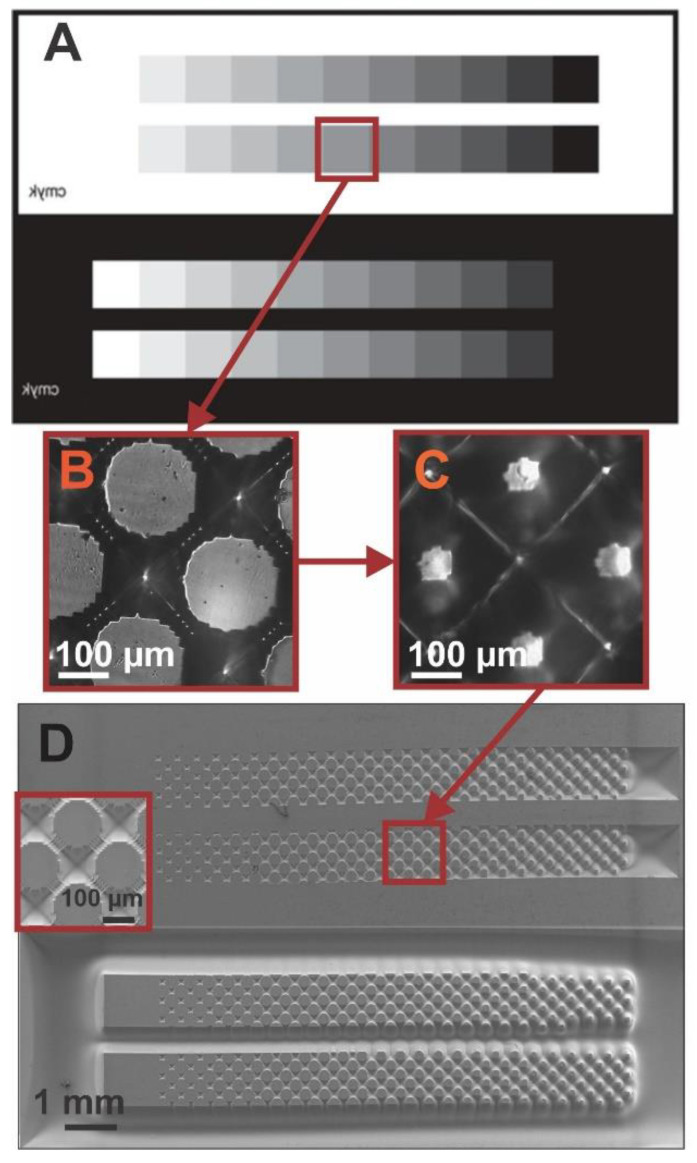
Figure 2.
(A) Design of the grayscale mask used. (B) Optical image of the resulting pattern in the photopolymer flexographic mold (Fmold). (C) Optical image of the resulting pattern in the epoxy resin mold (ER mold). (D) SEM image of the PDMS stamp. The inlet shows a magnification of the respective pattern obtained with the mask.

