
Figure 9.
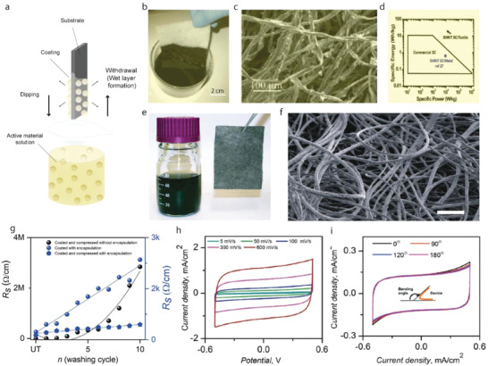
a) Schematic diagram of dip coating technique. b) Conductive textiles fabricated by dipping textile into an aqueous SWNT ink followed by drying in oven at 120 °C for 10 min. c) SEM image of coated cotton reveals the macroporous structure of the cotton sheet coated with SWNTs on the cotton fiber surface. d) Ragone plot of commercial SCs, SWNT SC on metal substrates, and SWNT SC on porous conductors including all the weight. Reproduced with permission.[ 223 ] Copyright 2010, American Chemical Society. e) Photograph of a stable, solution‐exfoliated graphene ink suspension prepared by ultrasonication of the graphite powder in a water sodium cholate solution, and a 6 cm X 8 cm graphene‐coated conductive textile sheet (polyester fabrics). f) SEM image of a sheet of graphene‐coated textile after 60 min MnO2 electrodeposition showing large‐scale, uniform deposition of MnO2 nanomaterials achieved on almost entire fabric fiber surfaces, Scale bar: 200 µm. Reproduced with permission.[ 224 ] Copyright 2011, American Chemical Society. g) The change in resistance with the number of washing cycles of G‐coated compressed (with encapsulation) poly‐cotton fabric, G‐coated only (with encapsulation) poly‐cotton fabric, and G‐coated compressed (without encapsulation) poly‐cotton fabric. h) Cyclic voltammograms (CV) recorded for the supercapacitor device at different scan rates i) CV curves for the ASC device at different bending angles. Reproduced with permission.[ 225 ] Copyright 2020, Wiley‐VCH.