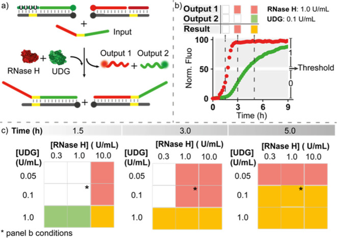
Figure 7.

Enzyme-mediated temporal control of a DNA logic circuit. (a) Scheme of the logic circuit. (b) Example of a time-course experiment at the indicated concentrations of RNase H and UDG. (c) Two-dimensional decision matrix obtained at three representative times using different concentrations of RNase H and UDG. Experiments were performed in Tris HCl 20 mM, MgCl2 10 mM, EDTA 1 mM, pH 8 at T = 30 °C. [Target duplexes] = 50 nM, [RNA-blocker] = 150 nM, [uracil-blocker] = 150 nM and at the indicated concentrations of RNase H and UDG.
