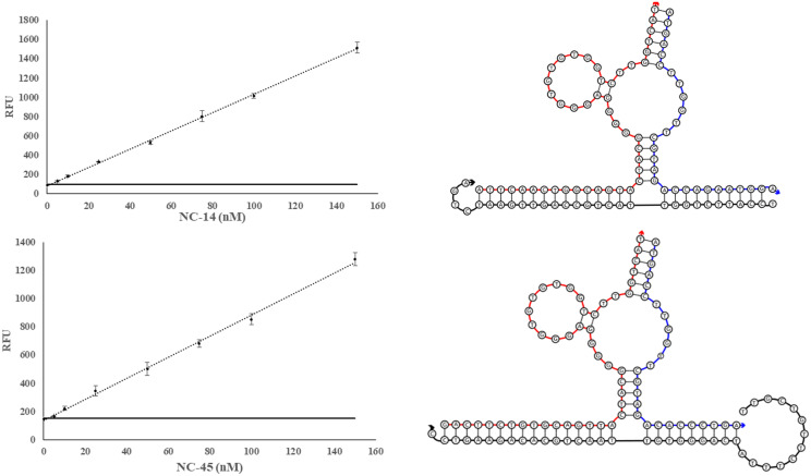
Fig. 6.
Calibration Curves of SDA4 and SDA3 sensors with sequence diagrams. Left depicts calibration curves for SDA4 (top) and SDA3 (bottom). The sequence diagrams of each sensor in complex with its target analyte (SDA4:NC-14 and SDA3:NC-45, top and bottom, respectively). The obtained LOD for SDA3 and SDA4 were 1.8 and 1.3 nM, respectively. The threshold signal, defined as the , is indicated by the horizontal solid line. The above curve is the average of 3 independent trials and was processed on Microsoft Excel. Fluorescence was recorded at 525 nm with an excitation at 475 nm.

