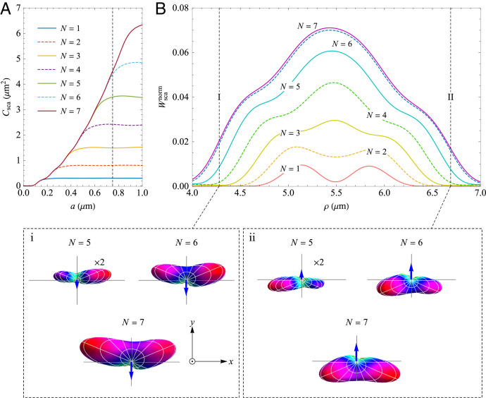
Fig. 3.
Multipolar analysis of the particle’s response. (A) Scattering cross-section of an Au particle with different sizes for plane-wave incidence. (B) Normalized scattered power from the particle of radius a = 0.75 μm, placed on the focal plane of the IPM vortex beam, versus its radial position for different N. Note the two vertical broken lines indicating the trapping positions I and II shown in Fig. 2A. The insets i and ii depict the angular distribution of scattered intensity in the far field for N > 4, when the particle is located at these trapping positions on the positive x axis, respectively. Because the scattered intensity for N = 5 is small, the size of its patterns is doubled to ease reading. Blue arrows illustrate the directions of the azimuthal recoiling force expected from the asymmetry of the pattern.

