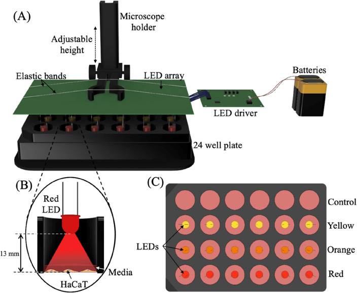
Figure 1.
Visible light exposure system. (A) Schematic showing the experimental set up, comprised of an LED array, LED driver, two 9 V and one 1.5 V batteries, and a microscope holder to position the LEDs above an opaque 24-well plate. (B) Cross-section of the inside of a well demonstrating position of LED and visible light exposure. There is a 13 mm gap between the LED tip and the HaCaT monolayer. (C) Top-down view of the LEDs and 24-well plate. Multiple different wavelength LEDs and sham exposures can be run in parallel on a single plate. The configuration for the experiments described herein include a control/sham condition, yellow light (585 nm), orange light (610 nm), and red light (660 nm).

