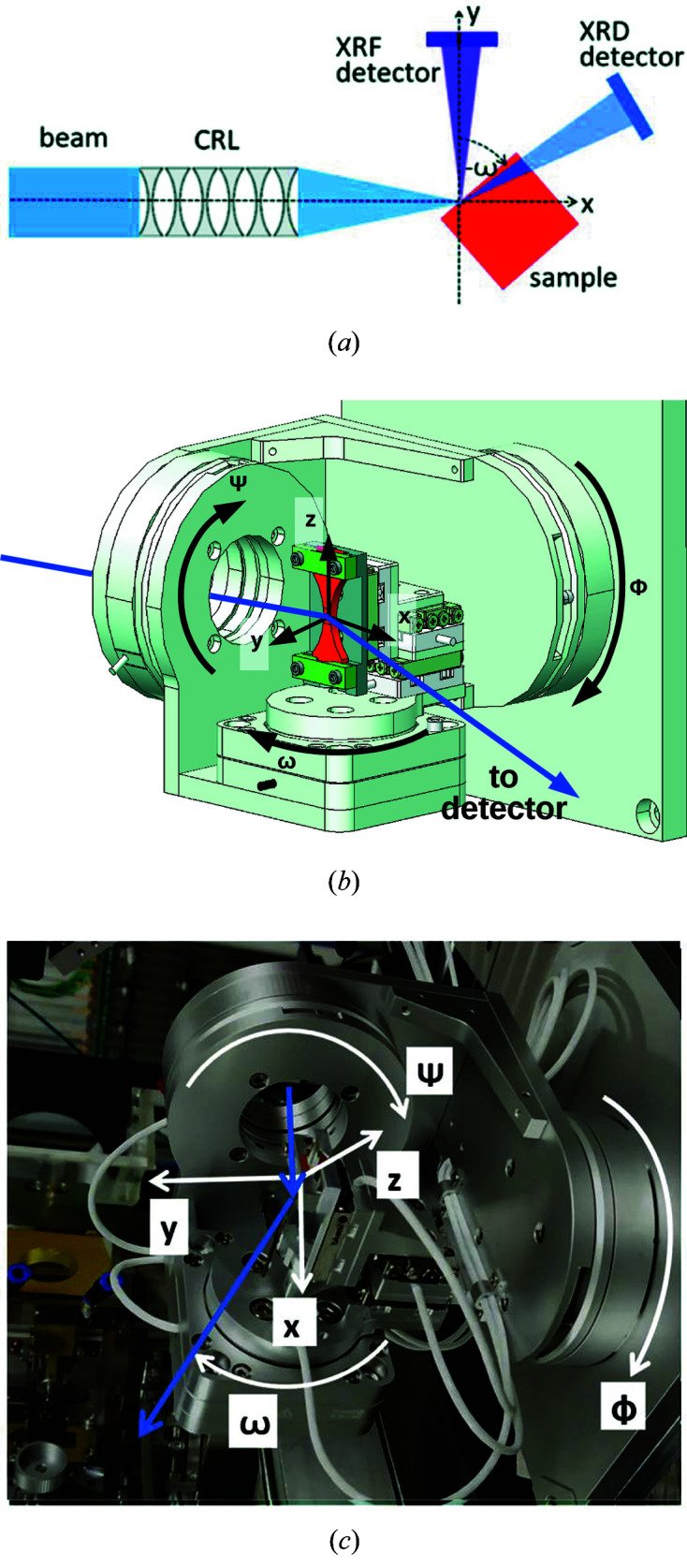
Figure 1.

(a) The setup geometry (top view). (b) A technical drawing of the goniometer. The positioners are stacked from outer to inner in the order Φ, Ψ, ω, y, x and z. (c) A photograph of the goniometer.

(a) The setup geometry (top view). (b) A technical drawing of the goniometer. The positioners are stacked from outer to inner in the order Φ, Ψ, ω, y, x and z. (c) A photograph of the goniometer.