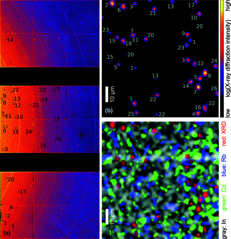
Figure 5.
(a) An XRD detector image summed over the mapped area of a solar cell with a polycrystalline ACIGS absorber layer. The rectangles with adjacent numbers denote diffraction peaks from individual ACIGS crystallites. (b) A real-space map of the XRD intensity with the crystallites attributed to their position in the reciprocal-space image shown in (a). For example, locations in (b) indicated by ‘1’ provide the Bragg peak in (a) indicated by the same number. (c) A combined map of the XRD intensity (red) with the elemental distributions of In (gray), Cd (green) and Rb (blue).

