FIG. 5.
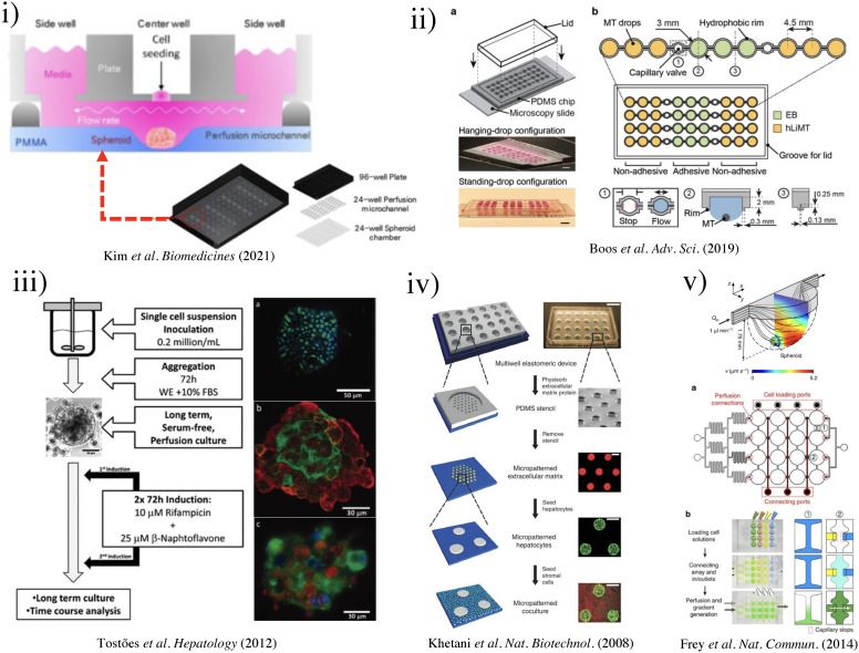
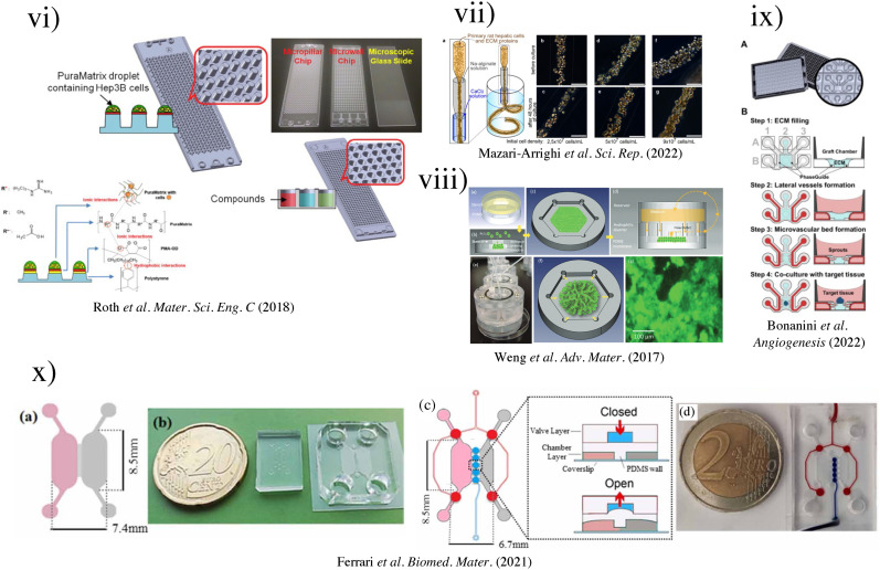
(i) Schematic of three-well array for the gravity-based spheroid culture.103 Reproduced with permission from Kim et al., Biomedicines 9(10), 1369 (2021). Copyright 2021 MDPI. (ii) Microfluidic multi-tissue hanging-drop platform. (a) The microfluidic network is patterned on the surface of a PDMS substrate. Photographs of the chip show its operation in hanging-drop and standing-drop configuration. Scale bar: 5 mm. (b) The chip layout consists of four individual lanes of nine interconnected drops.94 Reproduced with permission from Boos et al., Adv. Sci. (Weinh) 6(13), 1900294 (2019). Copyright 2019 John Wiley& Sons. (iii) Experimental design of the induction of the CYP450 enzymes in primary cultures of hepatocyte spheroids in the bioreactor (left). Scale bar = 50 μm. Immunofluorescence microscopy of liver-specific antigens in human hepatocyte spheroids after two weeks of bioreactor culture (right).153 Reproduced with permission from Tostões et al., Hepatology 55(4), 1227–1236 (2012). Copyright 2011 John Wiley & Sons; (iv) schematic of the process flow aside photomicrographs taken at each step. A reusable PDMS stencil is seen consisting of membranes with through-holes at the bottom of each well in a 24-well mold. Primary hepatocytes selectively adhere to matrix-coated domains, allowing supportive stromal cells to be seeded into the remaining bare areas (hepatocytes labeled green and fibroblasts orange; scale bar is 500 μm).102 Reproduced with permission from Khetani et al., Nat. Biotechnol. 26(1), 120–126 (2008). Copyright 2007 Springer Nature. (v) Numerically simulated streamlines and flow velocities of a perfused drop containing a 400-μm-diameter spheroid (the applied flow rate is 1 μl min−1; hanging drop has maximal size and a height of 1.75 mm). The same flow rate is applied at the outlet. Gray areas indicate contact walls with the no-slip condition (v = 0 μm s−1). (a) Layout of the four-by-four drop array, showing the added features for array reconfiguration (marked in red). (c) Three handling steps are required during an experiment (close-up views show key areas).98 Reproduced with permission from Frey et al., Nat. Commun. 5(1), 4250 (2014). Copyright 2014 Springer Nature. (vi) Schematic representation of the micropillar and microwell chip platform for use in Hep3B cell encapsulation in PuraMatrix and compound toxicity assessment.108 Reproduced with permission from Roth et al., Mater. Sci. Eng. C 90, 634–644 (2018). Copyright 2018 Elsevier. (vii) Encapsulating primary rat hepatocytes within core–shell hydrogel microfibers by applying cell fiber technology. (a) Schematic drawing of the fabrication of core–shell hydrogel microfibers encapsulating freshly isolated rat hepatocytes through a double-coaxial microfluidic device. (b)–(g) Representative dark-field images (n = 12 cell fibers for each group) of primary rat hepatocytes encapsulated in cell fibers before culture and after 48 h of culture in three experimental groups possessing different initial cell seeding densities: 2.5, 5, and 9 × 10⁷ cells ml−1. Scale bars; 100 μm.106 Reproduced with permission from Mazari-Arrighi et al., Sci. Rep. 12(1), 1–12 (2022). Copyright 2022 Springer Nature. (viii) Design principles of tissue incubator. (a)–(d) Schematic diagram of design principles. (e) Photo of entire device. (f) Schematic diagram of radial flow. (g) LOC shows good cell viability with Calcein AM staining (green).74 Reproduced with permission from Weng et al., Adv. Mater. 29(36), 1701545 (2017). Copyright 2017 John Wiley& Sons. (ix) The OrganoPlate Graft allows for the generation of robust microvascular beds. (a) Top and bottom views of the OrganoPlate Graft with 64 microfluidic units positioned underneath a 384 microtiter plate. Each microfluidic unit makes use of a 2 × 3 array of wells from the microtiter plate (the inset image). (b) Sequence of steps for generating a microvascular bed.93 Reproduced with permission from Bonanini et al., Angiogenesis 25(4), 455–470 (2022). Copyright 2022 Springer Nature. (x) Developed micropatterned devices. (a) Schematic of the microgrooves-based platform with pink: liver compartment and gray: tumor compartment; (b) picture of the microgrooves-based device and stamp for micropatterning; (c) concept of the valve-based platform with pink: liver compartment and gray: tumor compartment. In the zoom is shown the valve operating principle; (d) a picture of the valve-based device.154 Reproduced with permission from Ferrari et al., Biomed. Mater. 16(4), 045032 (2021). Copyright 2022 IOP Publishing, Ltd.


