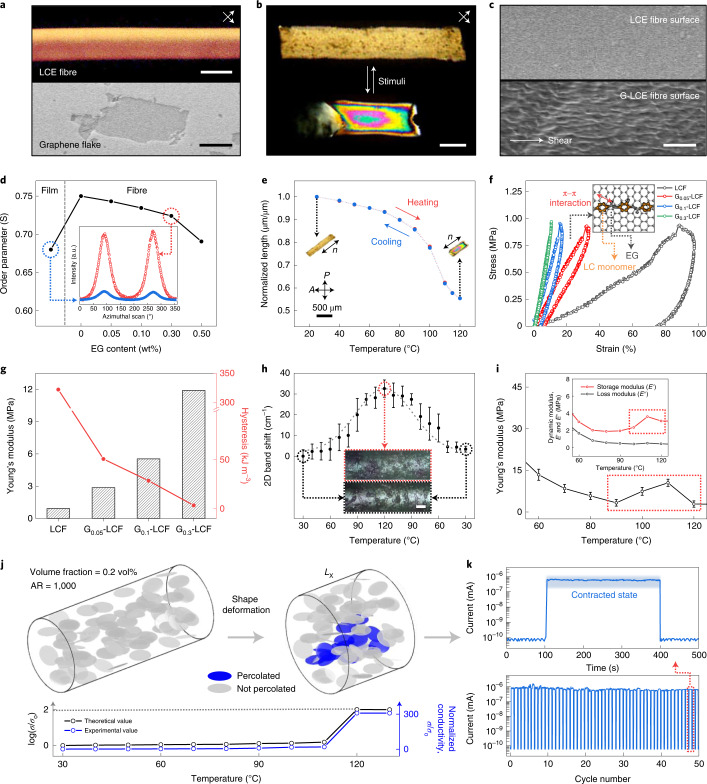
Fig. 2. Highly aligned LCF and G-LCFs with reversible electrical percolation.
a, POM image of LCF observed at 45° angles with respect to cross-polarizers (top) and SEM image of an EG flake (bottom). b, Shape deformation of G0.3-LCF under POM for relaxation and contraction. c, SEM image of LCF and G0.3-LCF surfaces. d, Orientational order parameters of LCF and G-LCFs from azimuthal scan profiles of 2D WAXS patterns. e, Reversible thermal actuation of highly aligned G0.3-LCF during stepwise steady-state heating and cooling cycle. f, Cyclic stress–strain curves for uniaxial tensile behaviours at 60 °C. The inset illustrates the π–π interaction between EG and LC mesogenic units. g, Young’s modulus and hysteresis level calculated from f. h, Raman 2D band shift against the contractive strain along the composite fibre as a function of temperature with the optical microscopy of relaxed and contracted states of G0.3-LCF. i, Variation in Young’s modulus and dynamic moduli of G0.3-LCF with temperature. j, Simulation for the reversible percolation of EG platelets under contractive actuation (volume fraction of 0.2% and aspect ratio (AR) of 1,000) along with theoretical and experimental values of electrical conductivity. k, Variation in electrical current of G0.3-LCF during reversible actuation over 50 cycles. Scale bars, 200 μm (top) and 2 μm (bottom) (a), 200 μm (b), 2 μm (c) and 50 μm (h). error bar=standard deviation for 10 measurements.

