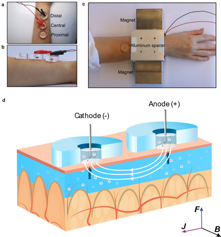
Figure 1.
Experimental set up and scheme. (a) Top-view of the acrylic wells placed on the volunteer’s lower arm. (b) A side-view of the acrylic wells. (c) The volunteer’s arm was placed between two neodymium magnets separated by an aluminum support. ( d) A schematic presentation of the set-up and the MHD extraction. Two Ag/AgCl disk electrodes inside the well drive a current through the skin (J). A magnetic field with direction (B) orthogonal to the current is applied to create Lorentz force (F) pointing towards the skin surface. The scheme is not drawn to scale. Figure Credits: Artic Frame Studio https://www.arcticframe.com.

