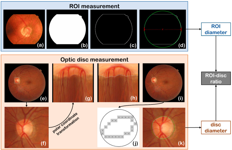
Figure 4.
Automated ROI measurement and optic disc measurement. (a–d) are the steps of detecting ROI, (e) shows the optic disc position target detection box annotation, (f) is the detected region of optic disc, (g–i) are the steps of disc edge detection in polar coordinate system, and (j,k) show the circumscribed circle fitting of the optic disc.

