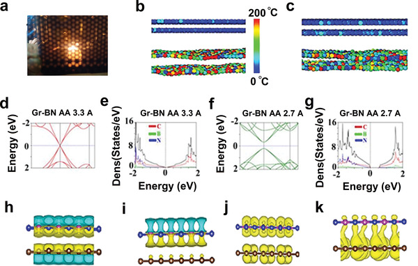
Figure 3.

a) Camera photo of the plasma generated during microwave processing. b) Molecular dynamics simulation for Gr‐BN solvothermally hybridized sample at equilibrium condition with average interlayer distance 3.3 Å and c) when hybridized, their interlayer distance locally decreased to 2.7 Å (color index exhibits localized temperature of the atoms). d) DFT band structure calculation for reduced Gr‐BN system considering AA stacking with interlayer distance 3.3 Å and e) DOS calculation for the Gr‐BN system with an insignificant band gap opening. f) DFT band structure calculation for AA stacking for Gr‐BN system with interlayer distance 2.7 Å in E‐k diagram exhibits parabolic dispersion with band gap opening and g) DOS calculation when the interlayer distance was 2.7 Å with AA stacking for Gr‐BN system which exhibits bandgap of 0.5 eV. h,i) Top and side views of charge density difference profile for Gr‐BN system in AA sequence with equilibrium distance 3.3 Å (electron transferred from Pz orbitals of Gr to Pz orbitals of BN). j,k) Charge density difference profile for reduced Gr‐BN system in AA stacking sequence with reduced distance 2.7 Å electron transfer from Pz orbitals of RGO to Pz orbitals of RBNO with physical bond formation due to strong interlayer coupling.
