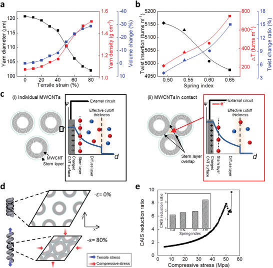
Figure 3.

Understanding the relationship between the inner structure and IEC change of coiled CNT yarn. a) Tensile strain dependence of the yarn diameter (black), yarn density (red), and volume change (blue) in L‐coiled yarn with a spring index of 0.65 during stretching 80%. b) Twist insertion (black), ∆T (red), and twist change ratio (blue) of L‐coiled yarns with spring indexes of 0.49, 0.54, 0.60, and 0.65. c) Conceptual illustration showing the change in the electrochemical double layer. The potential changes near the surface of MWCNTs (ψ) were depicted (i) when each MWCNT was far apart and (ii) when MWCNTs were adjacent to each other. The red and blue spheres represent negative and positive charges, respectively. d) The mechanism by which the tension of the L‐coiled yarn exerts a compressive strain on the cross‐sectional microstructure. As the compressive strain reaches 40%, the adjacent MWCNTs come into contact with each other, and compressive stress is generated. e) The CAIS reduction ratio under radial compressive stress. The equivalent value according to the spring index condition considered in the experiment is included as an inset.
