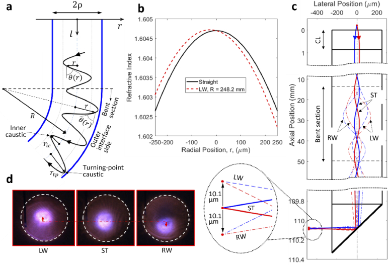
Fig. 3.
Perturbed ray paths due to lens bending. (a) Schematic showing the shift of ray trajectories toward the outer interface on the bend, (b) RI profiles of the RL with and without bending, (c) simulated ray trajectories with and without lens bending, inset showing enlarged view of the focus position, (d) experimental observation of bend induced focus shift. LW, bent leftward; RW, bent rightward; ST, straight.

