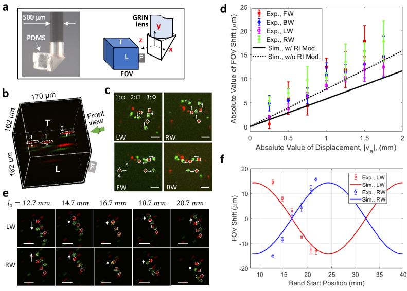
Fig. 4.
Demonstration of bend induced FOV shift. (a) An image of the fluorescent bead-imbedded PDMS attached to the prism surface for testing of FOV shift (left) and definitions of orientation and coordinates of the FOV (right), (b) an overlaid 3D image of fluorescent beads in PDMS, (c) front view of bead positions for different bending directions, (d) measured and simulated FOV shift as a function of the displacement, (e) front view of bead positions when the lens is bent at different locations, (f) measured and simulated FOV shift as a function of the bend location (represented by the bend start location, ). All scale bars: 20 µm. In all images of b, c, and e, red is for straight lens and green is for bent lens. LW, bent leftward; RW, bent rightward; FW, bent forward; BW, bent backward. For b and c, , (leftward bending).

