Figure 1.
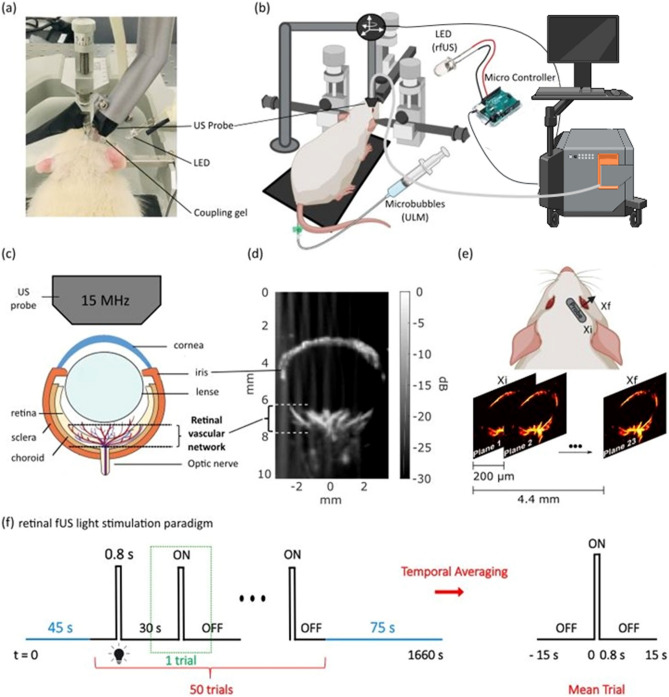
Ultrasound Localization Microscopy and fUS Imaging Set Up. (a) Picture of the experimental setup. The animal is anesthetized and placed in a stereotaxic frame for the correct positioning of the US probe. After eye drop and mydriatic instillation, the eye is covered with ophthalmic coupling gel. The probe is tilted to image the plane shown in (d). (b) Scheme of the entire setup. The probe is connected to a functional ultrasound scanner. The microbubbles solution is a contrast agent administered intravenously via one of the rat tail lateral veins for ULM. The LED delivers light flashes for rfUS imaging and is triggered by the scanner through a microcontroller (Arduino) for precise timings. (c) Scheme of the rat eye, its principal structures, and the imaging field comprising the retinal vascular network. (d) Doppler image of a rat eye. The retinal vascular network is visible. (e) ULM scanning details. The scan starts at the initial position xi in 200 µm steps along the mediolateral axis to the final position xf. (f) Retinal fUS imaging stimulation design. The acquisition consists of a baseline recording of 45 s followed by 50 consecutive trials and terminated by a recovery period of 75 s, during which the RBV is continuously recorded. One trial consists of 15 s OFF, followed by a short light flash of 0.8 s ON and another 15 s OFF. One acquisition lasts 28 min. The mean trial is obtained via temporal averaging of the successive single trials. Figure created with BioRender.com.

