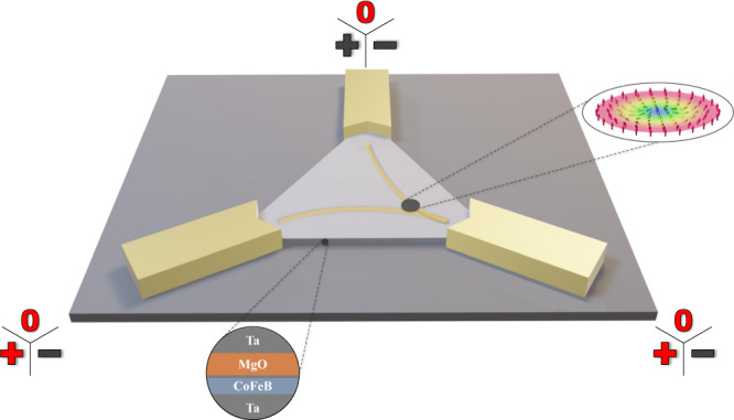
Fig. 1. Three-dimensional schematic of the device.

The stack structure is shown in the lower circle. Attached are the chromium/gold contacts, on which positive, negative, or null potential can be applied. The input values used for the present Boolean logic demonstration are highlighted in red. The dark gray spot in the triangle represents a skyrmion as imaged in our magneto-optical Kerr effect (MOKE) microscopy recordings. Here, it is pushed into the lower right corner (yellow lines represent schematically the current flow). The inset on the right depicts the schematic spin structure of a Néel-type skyrmion. Note: Inset adapted from the original of Karin Everschor-Sitte and Matthias Sitte, which is licensed under Creative Commons Attribution-Share Alike 3.0 Unported (CC BY-SA 3.0).
