. 2022 Nov 16;12(51):32925–32948. doi: 10.1039/d2ra05535j

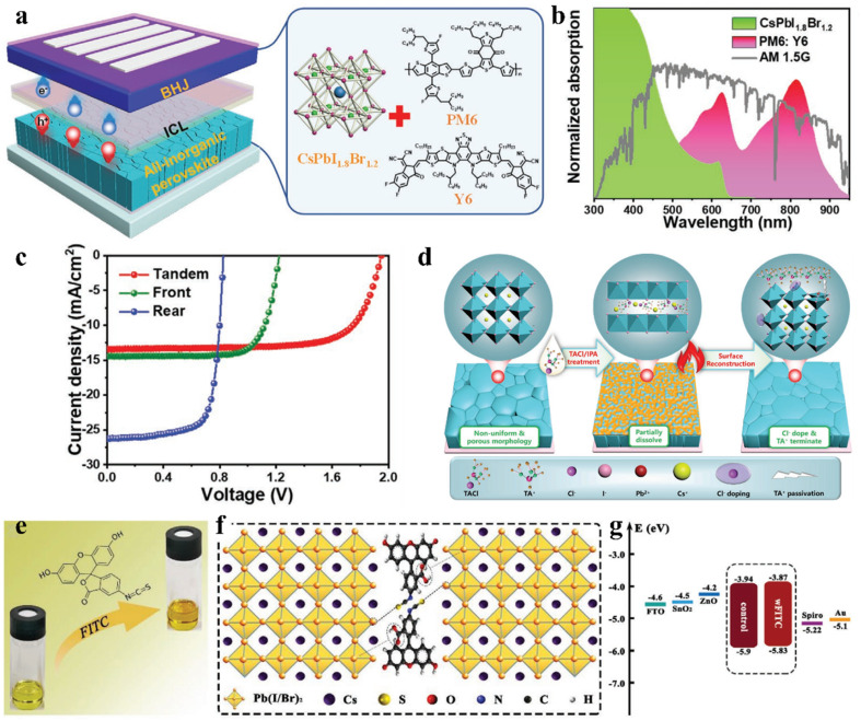
Fig. 7. (a). Left: device structure of all-inorganic perovskite/organic 2T TSC. Right: crystal structure of front all-inorganic perovskite CsPbI1.8Br1.2 and the molecular structures of the donor and acceptor materials in the rear cell. (b). Normalized absorption spectra of CsPbI1.8Br1.2 and PM6:Y6 films and the AM1.5G spectrum. (c). JV curves of 2T TSC, front and rear solar cells under AM1.5G 100 mW cm−2 illumination. (d). Schematic illustration of the TACl and IPA synergistically induced SR processes. (a–d) Reproduced with permission.89 Copyright 2022, Wiley-VCH. (e). Pristine perovskite solution (left) and perovskite/FITC hybrid solution (right). (f). Schematic illustration of the interaction between FITC and perovskite. (g). Energy level diagram constructed from UV-vis and UPS measurements. (e–g) Reproduced with permission.91 Copyright 2021, Wiley-VCH.

Fig. 7