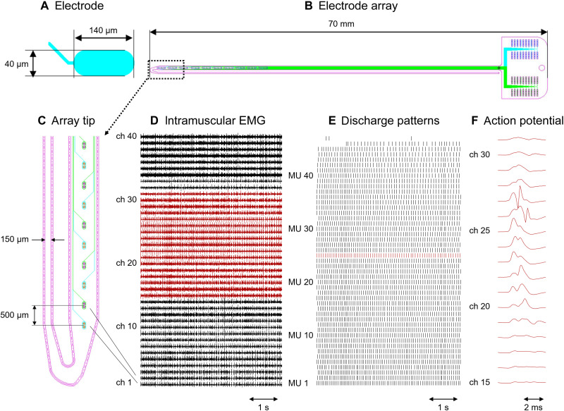
Fig. 1. Design of the double-sided electrode array and representative recordings.
(A) Close-up of an oval electrode. (B) Whole structures with the tracks running toward the connection pad. (C) Close-up of the electrode array tip. Electrodes represented in cyan are located on the top side of the thin-film array, and those in green are located on the bottom side of the wider filament. (D) Representative recordings obtained from the tibialis anterior of subject 1 (S1) during a contraction at 20% of the maximal force [maximal voluntary contraction (MVC)]. (E) Discharge pattern of 47 motor units (MUs) extracted from the signal shown in (D). (F) Multichannel action potentials of a representative MU obtained by averaging the red-colored EMG channels in (D) with the discharge pattern of the same color in (E) as a trigger. ch, channel.

