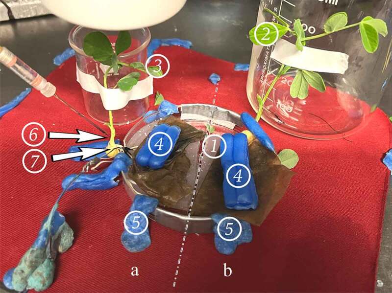
Figure 7.

Experimental setup.We denote the side of the dish with the glass electrode and ground wire (6 and 7) as “Side A.” The plant and agar island on the side of the setup not being recorded is denoted “Side B.” The demarcation between side A and B is denoted with the dashed line – representing the gap between the two islands of agar. Each plant is fixed in position with tape and a beaker for stem support. Wax is used to secure the dish to the testing surface which rests on an air table. The numbers indicate where different controls are performed:.
- A patch of agar suitable for performing an agar touch on the side B.
- A leaf suitable for a leaf nudge and leaf snip on Side B.
- A leaf suitable for a leaf nudge and leaf snip on Side A.
- Surgical wax is used as weights to hold down the roots under the paper towel, and to keep the roots in good contact with the agar they rest on.
- Surgical wax used to secure the setup to the testing pad.
- Glass electrode inserted into the plant stem on Side A.
- Reference electrode adhered with silver paste to the taproot of the plant
