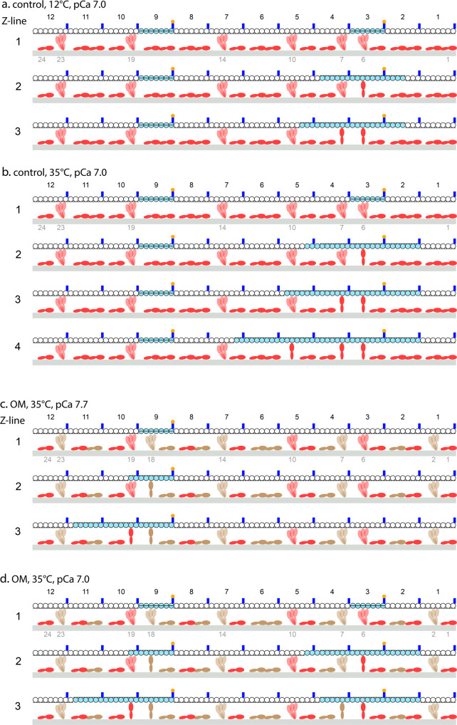
Fig. 5. Mechanistic model to explain the dependence of the cooperativity (nH) on the force per myosin motor (F0) and the inhibitory effect of OM.
In each line of a–d: the upper filament is the thin filament with monomers (circles) either blocked (white) or available for myosin attachment (cyan), Tm, black line shifted according to the three states (down blocked, middle closed, up open). Tn complex, blue, Ca2+, yellow. The filament is reduced to 12 RU’s for simplicity (identified by black numbers from 1 to 12 in the Z-ward direction); the lower filament is the thick filament (grey) carrying two myosin molecules per RU (red without OM, brown OM-bound) identified by green numbers from 1 to 24 in the Z-ward direction. The 18 molecules lying on the surface of the thick filament represent those not available for actin attachment, the 6 that emerge from the backbone are those that attach to an actin site once it is made available by Tm displacement (black line moves up) caused by either Ca2+- activation of the RU or the cooperative action of a nearby attached motor. In each panel, line 1 represents the starting conditions at a given pCa and the subsequent lines represent the sequence of events triggered by activation and myosin attachment until a steady state for that pCa is attained. a and b, in control solution at pCa 7 and 12 °C and 35 °C respectively. c and d, in the presence of 1 μM OM at 35 °C and pCa 7.7 and 7 respectively.

