
Fig. 2 |. The fabrication process of a gut-on-a-chip and a hybrid chip.
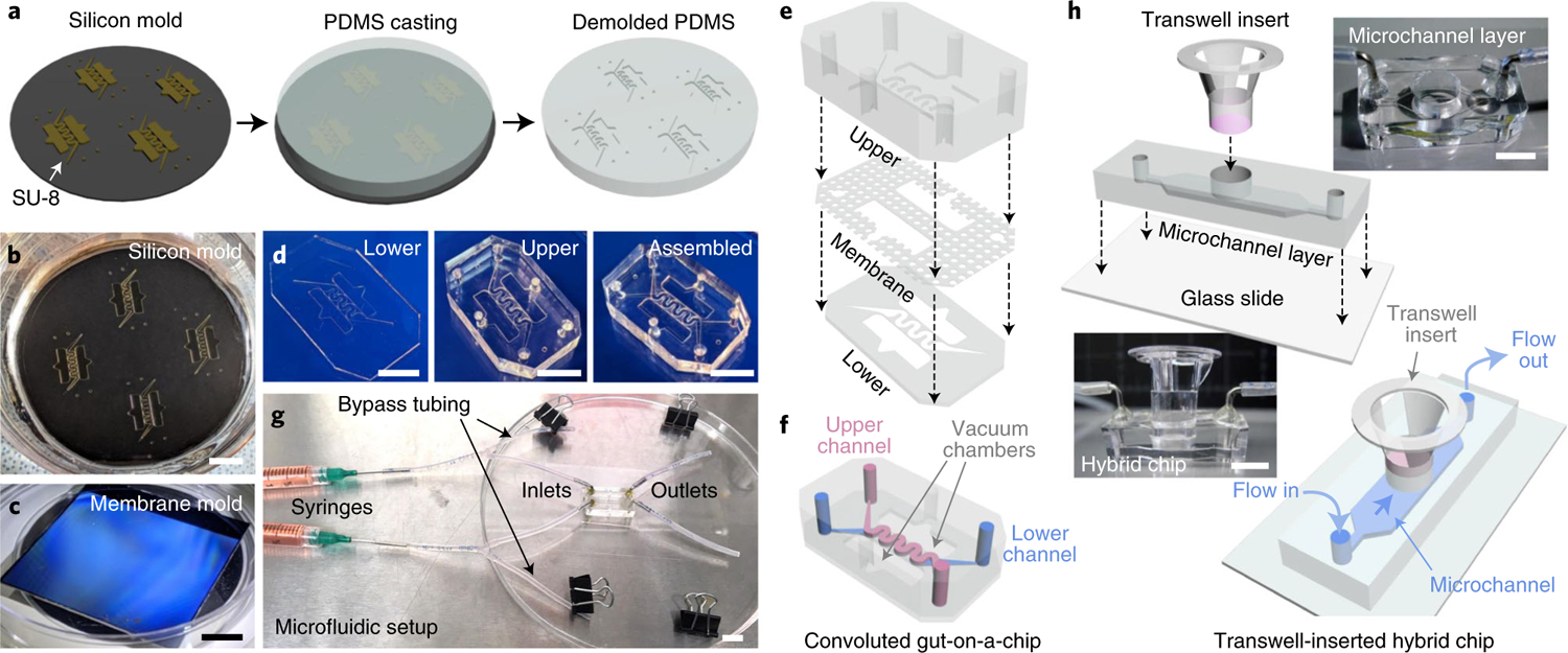
a, A schematic to prepare a PDMS part from a SU-8-patterned silicon mold. Uncured PDMS solution is poured on a silicon mold (left), cured at 60 °C (middle) and demolded (right). The demolded PDMS is cut into several pieces and cleaned for further use. b, A photograph of a silicon mold for preparing an upper PDMS layer. c, A photograph of a silicon mold for fabricating PDMS porous membranes. d, A series of photos of upper and lower PDMS parts as well as an assembled gut-on-a-chip device. e, A schematic diagram of the alignment of the upper, membrane and lower PDMS parts. Each layer is irreversibly bonded by either plasma or corona treatment. f, A schematic of a fabricated gut-on-a-chip device that has superimposed convoluted microchannels and vacuum chambers. g, Setup of a gut-on-a-chip for microfluidic cell culture. The fabricated gut-on-a-chip assembled with silicone tubing and syringes is placed on a cover slip. The chip setup is placed on a lid of a 150 mm Petri dish for handling. Binder clips are used to close the silicone tubing. h, A visual snapshot of the fabrication of a hybrid chip and the use of a hybrid chip for 3D morphogenesis. A Transwell insert that is independently prepared to culture a 2D monolayer of intestinal epithelial cells is inserted into a hybrid chip to induce intestinal 3D morphogenesis. Culture medium is perfused through the microchannel underneath the cell layer established on the Transwell insert. Scale bars, 1 cm. h reproduced with permission from ref. 4, Elsevier.