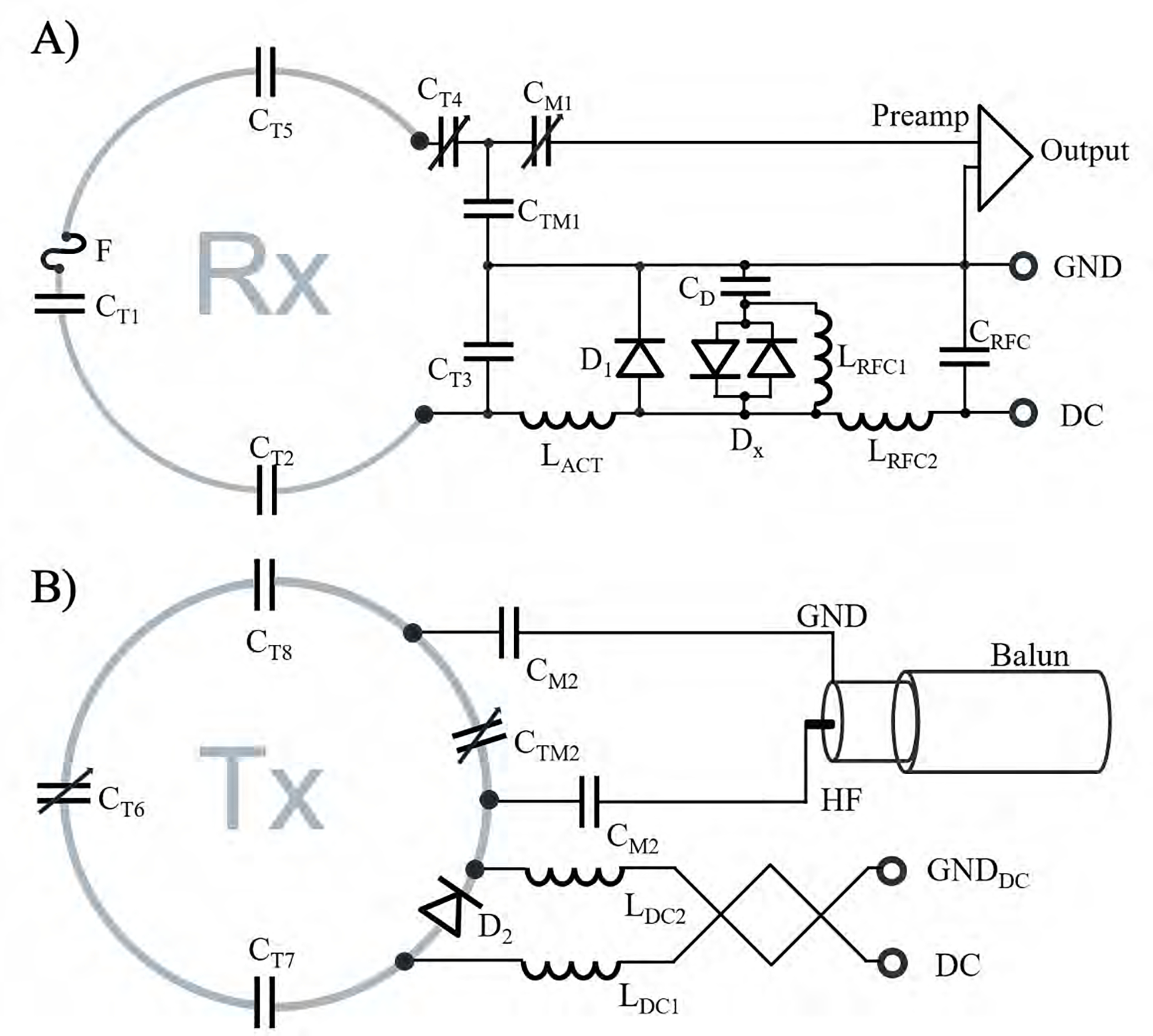
Figure 4:

Circuit schematics of the Rx loop element (A) and Tx coil (B). Rx loop elements consist of tuning capacitors (CT1, CT2, CT3, CT4, CT5), an active and passive detuning circuitry (D1, DX, CD, LRFC1), and a fast-switching RF-fuse (F). The Tx elements consist of series tuning capacitors (CT6, CT7, CT8), a PIN diode (D2) for active tuning, a balanced drive port with two matching capacitors (CM2), and a “bazooka balun” to eliminate common mode RF cable currents. The RF choke LRFC1 is needed to provide a stable DC voltage potential between the X-diode and the capacitor CD during the bias switching transient.
