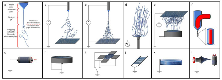
Figure 2.
Electrospinning and electrospraying. (a) Diagram of the section of electrospinning process; (b) typical electrospinning setup depicted with an electrified spinneret, a grounded plate collector, and a high-voltage DC power source; (c) typical electrospraying setup depicted with an electrified sprayer, a grounded plate collector, and a high-voltage DC power source; (d) typical electrospinning set-up depicted with an electrified spinneret, a grounded plate collector, and a high-voltage AC power source; (e) a form of needleless electrospinning set-up depicted with an electrified sprayer, a grounded plate collector, and a high-voltage DC power source; (f) coaxial electrospinning/electrospraying; (g–l) other options for electrospinning collectors include (g) rotating and rastering mandril collector (rastering is optional), (h) cup-and-pin collector, (i) perpendicular collector, (j) parallel collector, (k) wet electrospinning, and (l) yarn electrospinning.

