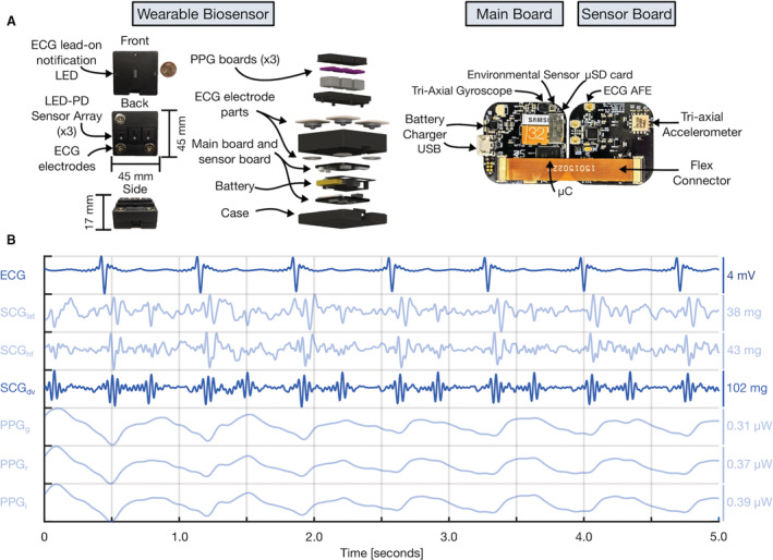
Figure 2. Wearable multimodal hardware engineering mechanics.

A, Pertinent multimodal hardware diagram. Final wearable biosensor iteration with exploded view detailing photoplethysmogram (PPG) components, gel‐electrode ECG connectors, lithium‐polymer battery, and printed circuit boards (PCBs). Main PCB with ATSAM4LS8 microcontroller (μC), BMG250 triaxial gyroscope and BME280 environmental sensor, micro secure digital card (μSD), and BQ24232 battery charger. Sensor PCB, connected to main PCB via flexible connector, with ADXL355 accelerometer, ADS1291 analog front end, and magnetic wire connections to separate PCB containing SFH7016 multichip light‐emitting diode (LED) and SFH 2703 photodiode (PD) used to acquire triaxial seismocardiogram (SCG), single‐lead ECG, and multiwavelength sternum PPG signals, respectively. B, Sample 5 seconds of filtered wearable signal data from a single‐ventricle patient with corresponding amplitudes are shown. In order from top to bottom: ECG, lateral SCG (SCGlat), head‐to‐foot SCG (SCGhf), dorso‐ventral SCG (SCGdv), green PPG (PPGg), red PPG (PPGr), and infrared PPG (PPGi) signals. The darker blue ECG and SCGdv signals are those used in this work. USB indicates universal serial bus.
