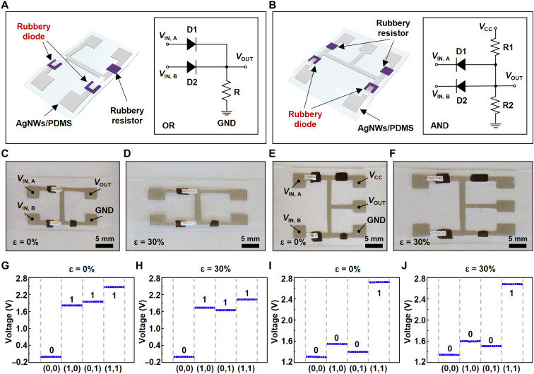
Fig. 3. Rubbery logic gates.
(A and B) Schematic illustrations of the rubbery OR gate (A) and AND gate (B). (C and D) Optical images of the rubbery OR gate under the mechanical strain of 0% (C) and 30% (D). (E and F) Optical images of the rubbery AND gate under the mechanical strain of 0% (E) and 30% (F). (G and H) Output characteristics of rubbery OR gate under the mechanical strain of 0% (G) and 30% (H). (I and J) Output characteristics of rubbery AND gate under the mechanical strain of 0% (I) and 30% (J). GND is short for ground.

