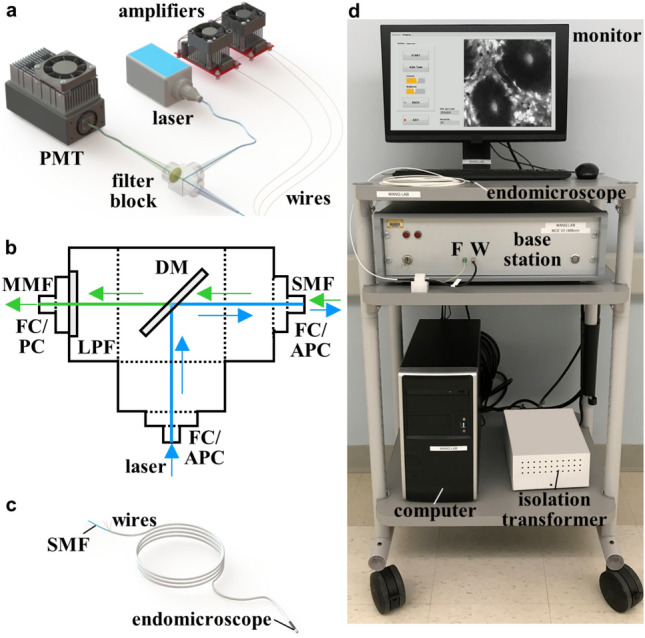
Figure 6.

Imaging system. (a) The PMT, laser, and amplifiers are contained within the base station. (b) In the filter block, the laser (blue) delivers excitation via a fiber pigtail via a FC/APC connector. The beam is deflected by a dichroic mirror (DM) into a single mode fiber (SMF) via a second FC/APC connector. Fluorescence (green) passes through the DM and a long pass filter (LPF) to the PMT via a multimode fiber (MMF). (c) The proximal end of the endomicroscope connects to the fiber (F) and wire (W) ports of the base station. (d) The endomicroscope, monitor, base station, computer, and isolation transformer are contained on a portable cart. (a, c) Solidworks 2016 was used for 3D modelling of the imaging system assembly and the endomicroscope.
