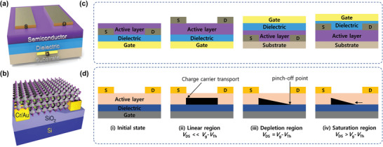
Figure 18.

Structure and operational mechanism of FETs. a) Cross‐sectional schematic of a typical FET. Reproduced with permission.[ 216 ] Copyright 2016, Wiley‐VCH. b) FET structure of hybrid perovskite FET. Reproduced with permission.[ 217 ] Copyright 2016, Nature Publishing Group. c) Schematic illustrations of the four types of common FET configurations: (from left) bottom‐gate bottom‐contact (BGBC), bottom‐gate top‐contact (BGTC), top‐gate bottom‐contact (TGBC), and top‐gate top‐contact (TGTC). d) Schematic representations of FET operating regions: i) initial state, ii) linear region, iii) depletion region, and iv) saturation region.
