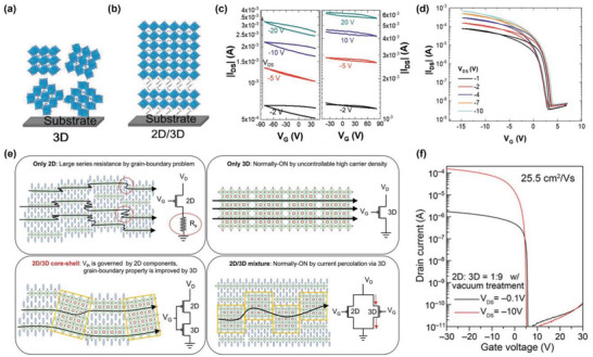
Figure 22.

2D/3D hybrid FASnI3/(PEA)2SnI4 FET. Schematic representation of phase distribution and orientation in a) only 3D film. b) 2D/3D film. Transfer characteristics of BGBC FET with c) only 3D FASnI3 as an active layer d) 2D/3D hybrid (PEA)2SnI4/FASnI3 as an active layer with optimized thickness. a–d) Reproduced with permission.[ 97 ] Copyright 2021, Wiley‐VCH. e) Schematic illustration of grain morphologies in cross‐sectional view of 2D (top‐left), 3D (top‐right), 2D/3D core–shell (bottom‐left) and 2D/3D mixture (bottom‐right) Sn‐based perovskite thin films. f) Transfer characteristics of 2D/3D core–shell FET with 2D/3D ratio of 1:9 and vacuum treatment. e,f) Reproduced under the terms of the Creative Commons CC‐BY license.[ 261 ] Copyright 2022, The Authors. Published by Wiley‐VCH.
