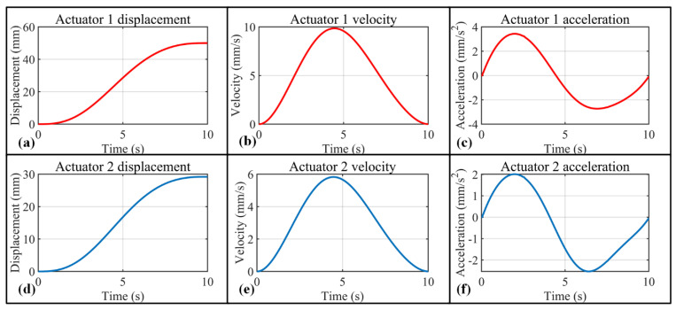
Figure 10.
Displacement, velocity, and acceleration diagrams of the two actuators in order to rotate 60° in 10 s for MCP and PIP joints. (a) Displacement–time diagram of actuator 1; (b) velocity–time diagram of actuator 1; (c) acceleration–time diagram of actuator 1; (d) displacement–time diagram of actuator 2; (e) velocity–time diagram of actuator 2; (f) acceleration–time diagram of actuators 2.

