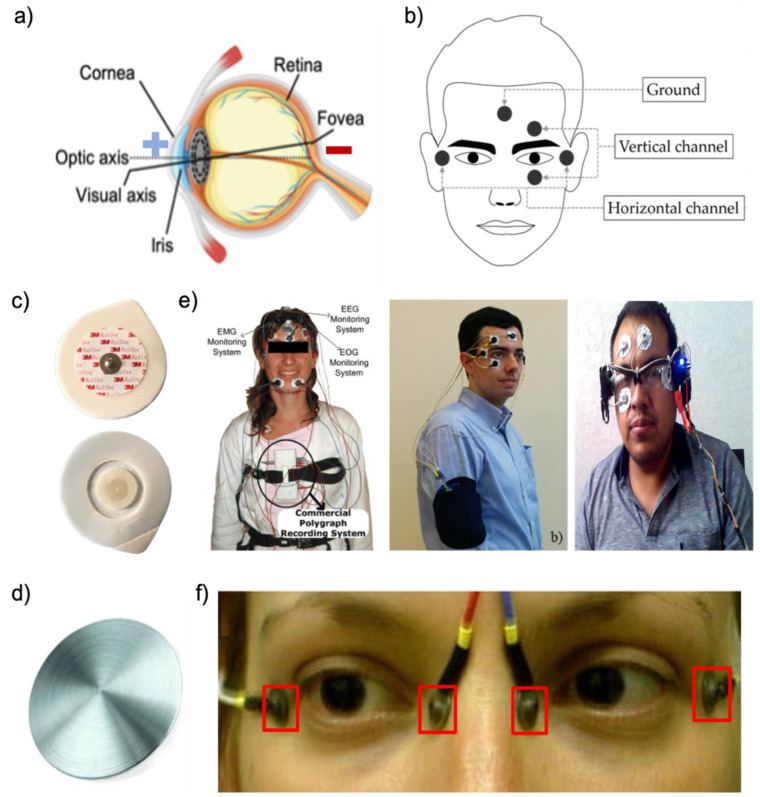
Figure 2.
EOG detection systems. (a) An anatomical illustration of the eye (cornea being positive and retina being negative). (b) Positions of electrodes for EOG detection (reprinted under terms of the CC-BY license [51]. Copyright 2017, the authors. Published by MDPI). (c) Conventional Ag/AgCl electrodes. (d) Example of a stiff material (metal disc) (Reprinted with permission [86]. Copyright 2013 Institute of Physics and Engineering in Medicine). (e) Exiting EOG devices with conventional gel electrodes (Left: Reprinted with permission [81]. Copyright 2009 Elsevier, Middle: reprinted with permission [60]. Copyright 2018 Elsevier, Right: reprinted under terms of the CC-BY license [37]. Copyright 2021, the Authors. Published by MDPI). (f) Exiting EOG devices with dry metal electrodes (Reprinted under terms of the CC-BY-NC license [87]. Copyright 2018, the Authors. Published by Springer Nature).

