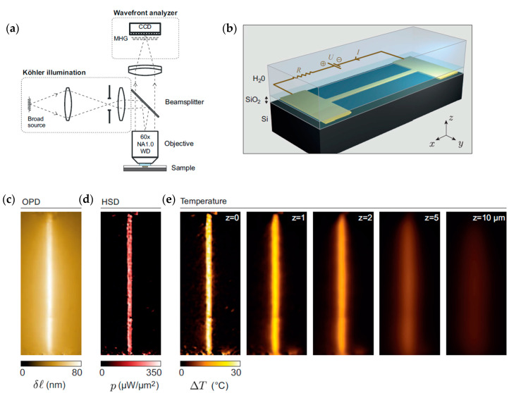
Figure 20.
(a) Schematic of the experimental setup developed by Bon et al. [114]; (b) gold microwire embedded in a layer of SiO2 and connected to two gold electrodes; (c) optical path difference (OPD) image; (d) heat source density (HSD) image obtained from the OPD; (e) temperature distribution at various heights from z = 0 (microwire position) obtained from the HSD images. Adapted and reprinted by permission from Ref. [114], Applied Physics Letters, Copyright © 2022 AIP Publishing LLC.

