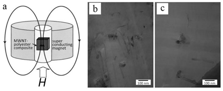
Figure 17.
(a) Schematic of the alignment of CNTs in composite under magnetic field. TEM image of a thin film sliced (b) parallel and (c) perpendicular to the applied magnetic field. Reproduced with permission [116]. Copyright 2002, John Wiley and Sons.

