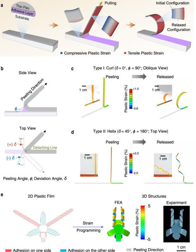
Fig. 1. Mechanism of peeling-induced shape morphing of plastic films.
a Schematic showing the peeling process involving the adherent thin film, adhesive layer, and substrate. The thin film is bent at the detaching area causing asymmetric deformation (tension and compression) on the two sides. The asymmetric plastic strain remains in the film after releasing and leads to the bending of the film. b Schematic showing two important control parameters: the peeling angle, ϕ, indicates the supplementary dihedral angle between the detached part and adhered part of the plastic film; the deviation angle, δ, indicates the angle measured from the short axis of the adherent film to the detaching line. According to the definition of peeling directions, the peeling process can be divided into two categories: δ = 0° and δ ≠ 0°. c, d Experimental and FEA results showing the peeling of a plastic PI film (30 μm thick, 5 mm wide) from Kapton tape at ϕ = 90° and δ = 0° (c) and ϕ = 180° and δ = 45° (with peeling force perpendicular to the long axis of the film) (d) during peeling (left) and after release (right). Peeling induces plastic deformation in PI and results in curling at δ = 0° and helix at δ = 45°. Insets: photographs of plastic PI film during and after peeling, respectively. e An orchid-like architecture with configurations of bending and helix from a 2D precursor film by peeling. Colors in the 3D FEA indicate the maximum principal plastic strain.

