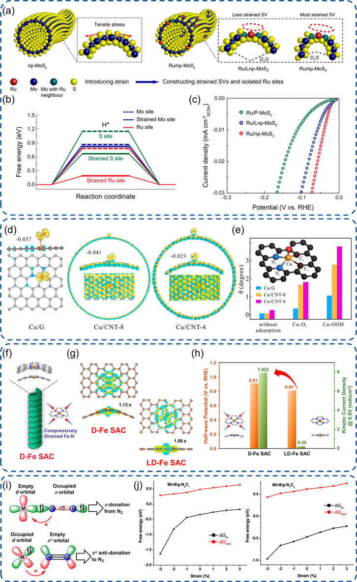
Figure 2.
Engineering of SACs with tensile surface strain or compressive strain. (a) Schematic illustration of Ru SAC construction with tensile stress, (b) free energy profiles for hydrogen adsorption, and (c) ECSA-normalized polarization curves for Ru SACs.73 (d) Side view and top view of the charge density difference of Cu SACs with different strains and (e) structure distortion of Cu sites at various stages of the ORR.77 (f) Schematic illustration of D-Fe SAC with compressive strains, (g) charge density difference diagrams of Fe SACs with electron accumulation or depletion highlighted by yellow or cyan, and (h) half-wave potentials and kinetic current densities (0.9 V vs RHE) of Fe SACs in 0.1 M KOH.81 (i) Schematic illustration of the fixation and activation of N2 on active sites with two models and (j) simulated ΔG with varying extra strain from −3 to 3% on Mn SACs with g-N3C1 and g-N1C3 two configurations.82 (a-c) Reproduced with permission under a Creative Commons CC BY License from ref (73). Copyright 2021 the Authors. (d-e) Reproduced with permission under a Creative Commons CC BY License from ref (77). Copyright 2021 the Authors. (f-h) Reproduced with permission from ref (81). Copyright 2021 Wiley-VCH. (i-j) Reproduced with permission under a Creative Commons CC BY-NC-ND 4.0 License from ref (82). Copyright 2021 American Chemical Society.

