
Fig. 3. Cryo-electron and negative stain electron microscopy validation of large HALs.
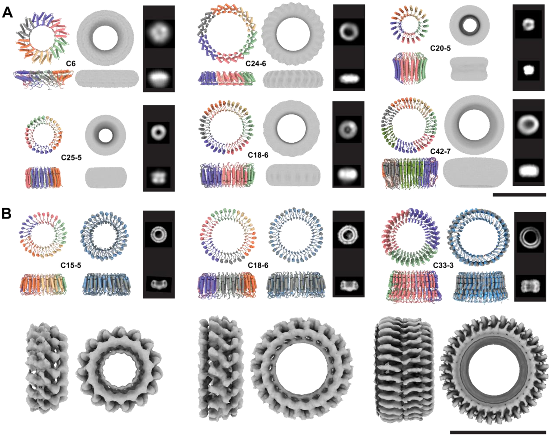
For each design, the model is shown colored by chain and the corresponding internal symmetry (X) and oligomerization state (Y) are indicated (CX-Y). The electron density map is shown next to the model alongside characteristic 2D class averages. (A) Negative stain characterization of HALs. Ring diameters are 92 Å, 110 Å, 75 Å, 80 Å, 100 Å, 107 Å, for HALC6_220, HALC24–6_316, HALC20–5_308, HALC25–5_341, HALC18–6_278 and HALC42–7_351, respectively. (B) CryoEM characterisation of three large HALs. The ring diameters are 87 Å, 99 Å, and 100 Å for HALC15–5_262, HALC18–6_265, and HALC33–3_343, respectively. Top row left panels: design model colored by chain; Top row, right panels: superpositions of the CryoEM model (gray) and design model (blue). The computed backbone atom RMSD between the designed and experimental structure are 0.81 Å, 1.69 Å, and 2.30 Å respectively (Fig. S16). Bottom row: 4.38 Å, 6.51 Å, and 6.32 Å cryoEM electron density maps. Scale bars = 10 nm.