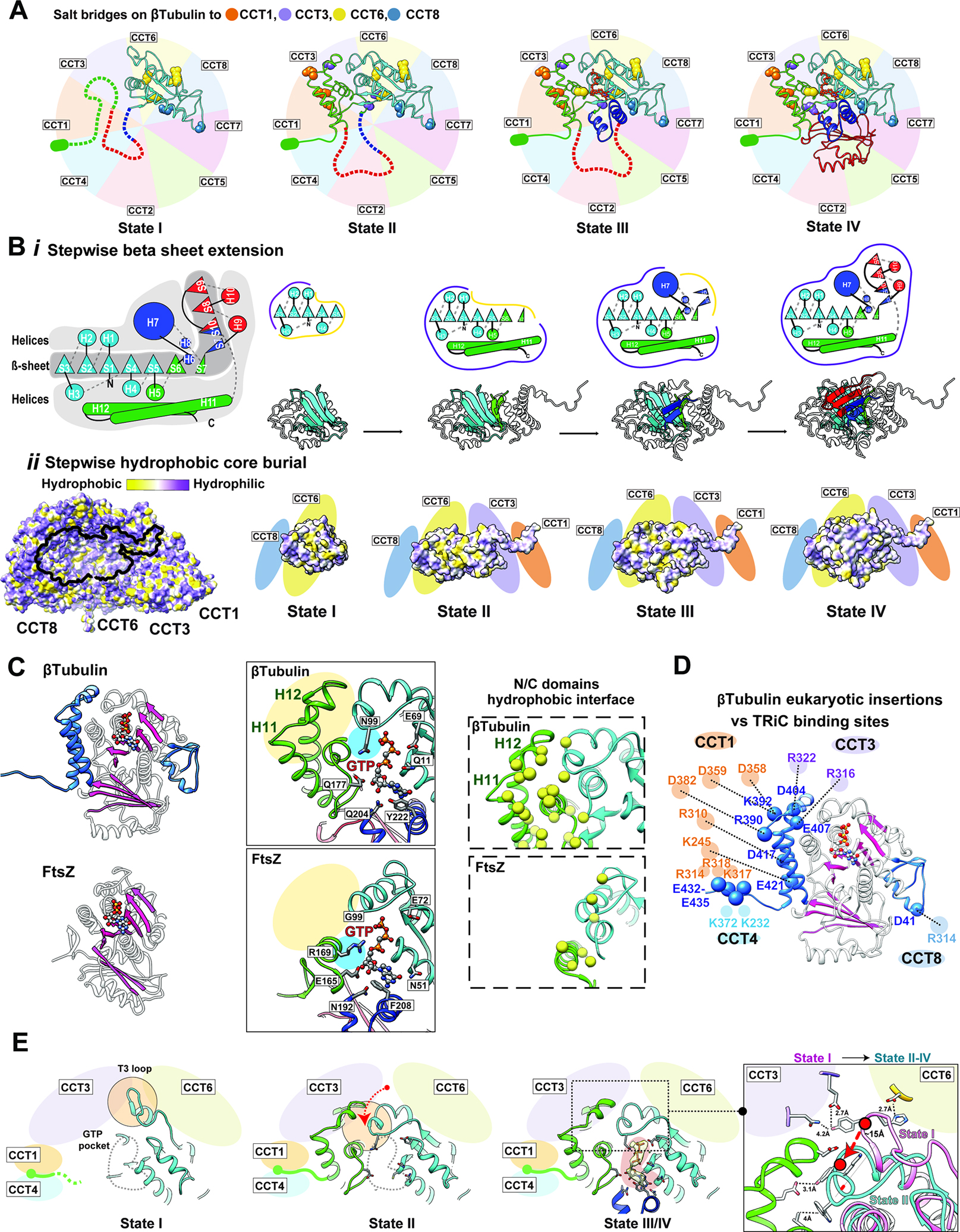
Figure 6: The directed folding of β-tubulin intermediates by specific CCT interactions.

(A) Specific contacts between β-tubulin domains and CCT subunits at each intermediate state; salt bridges shown as balls colored according to the interacting CCT subunit. Not yet folded domains of each state shown as dotted lines. The negatively charged E-hook annotated as a green ellipse. (B) (i) Cartoon of β-tubulin emphasizes the hydrophobic β-sheet running the length of the β-tubulin structure that is surrounded by α−helices, and individual cartoons for the sequential formation of this β-sheet core through each folding state. (ii) Hydrophobicity distribution on TRiC of the β-tubulin interacting surface, and the hydrophobic core burial of β-tubulin as it extends towards the interior of the chamber through the folding states. (C) Ribbon diagram of β-tubulin (PDB 6I2I36, top panel) and FtsZ (PDB 1FSZ48; bottom panel); additions unique to β-tubulin structure shown in blue. The overall β-strand folds in β-tubulin and FtsZ are colored in pink. Zoom-in views of the GTP binding pocket (contacting residues indicated) and N/C-domain interface (hydrophobic residues yellow) are shown for comparison. (D) The contacts between β-tubulin specific insertions and CCT subunits are shown with potential salt bridges. (E) Formation of the β-tubulin GTP binding pocket through β-tubulin intermediates. GTP pocket is indicated as a gray dotted line in states I and II, density map corresponding to the nucleotide displayed as a yellow density with pink background in state III/IV. T3 loop makes a large conformational change between state I and the other states indicated by the red arrow and displayed in the focused overlay between states I and II-IV.
