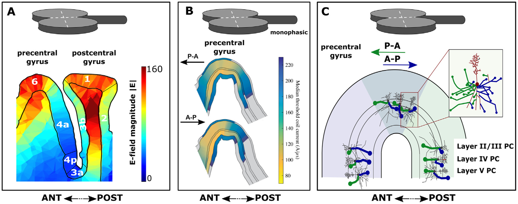
Fig. 1. Sagittal view on the pre and postcentral gyrus illustrating key biophysical features of transcranial magnetic stimulation (TMS).

The sagittal slice cuts through the motor hand knob which hosts the precentral motor hand representation. Panel A. Spatial pattern of the electric field magnitude (|E|) induced by TMS in both precentral and postcentral gyrus (generated with SimNIBS software). Note that the highest field strengths are obtained in the crowns of the pre- and postcentral gyri. The illustration also shows that significant “hot spots” may arise in subcortical white matter, although the activation threshold there is likely to be different than in the gray matter due to differences in the represented neural elements. The numbers indicate the various cyto-architectonically defined cortical areas according to Brodmann. Panel B. Layer-specific distribution of activation thresholds in relation to induced current direction in the hand knob of the pre-central gyrus. Shown are median thresholds for layers 1–6 on analysis plane through pre-central gyrus, parallel to coil handle and near coil center for monophasic stimulation with posterior-anterior (P-A) and anterior-posterior (A-P) current directions. The thresholds were simulated with a multi-scale model coupling electric field distribution from Panel A to morphologically realistic cortical neuron models in NEURON software. Modified from Aberra and colleagues (2020) with permission. Panel C. Direction-specific depolarization of axon terminals illustrated for pyramidal cells (PC) in cortical layers II/III, IV and V. Pyramidal cells, including their axonal arborization, are “projected” into the anterior (light blue) and posterior part (light green) of the precentral gyrus, forming the posterior wall of the precentral gyrus or anterior wall of the central sulcus, respectively. The same cells are also projected onto the crown of the precentral gyrus (grey area). Depending on the induced current direction in the precentral gyrus, different terminals of axonal branches are primarily depolarized by the TMS-induced electric field. These axons are highlighted as bold blue and green lines according to induced current directions. Axon branches susceptible to a posterior-anterior (P-A) current direction in the gyrus are labeled in blue and axon branches susceptible to anterior-posterior (A-P) current direction are labelled in green. The dendritic tree, soma and axonal branches perpendicular to the P-A and A-P directions are labeled in grey and red color. From a biophysical modeling perspective, the axon terminal mechanism of action potential induction illustrated in this panel is a key mechanism by which TMS induces action potentials, but it does not exclude additional mechanisms (e.g. excitation at axonal bends), especially at high intensities of stimulation. The illustration is inspired by results from the multi-scale model depicted in Panel B. Please note that the real size of the TMS coil is much larger. ANT: anterior, POST: posterior.
