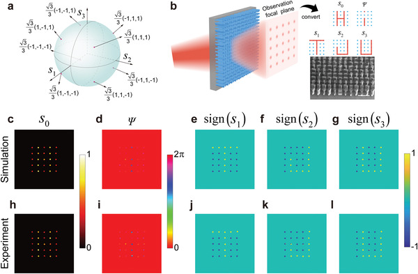
Figure 4.

Five‐channel imaging meta‐hologram. a) Eight selected polarization states on a standard Poincare sphere to be generated in the spot array image. b) Schematic of the function of the five‐channel imaging meta‐hologram. The inset shows the tilted SEM image of part of the fabricated meta‐hologram. Scale bar: 300 µm. c–g) Extracted spot array images in the s 0, Ψ, s 1, s 2, and s 3 channels from the simulated CVF distribution at the imaging plane at 1.0 THz. Only the corresponding values around the spot positions are presented. For the images in the s 1, s 2, and s 3 channels, they are calculated by taking sign function of the extracted values. Clearly images of five letters “Hi TJU” are obtained. h–l) Corresponding measured results to (c–g) at 1.05 THz. The incident polarization is x‐polarized.
