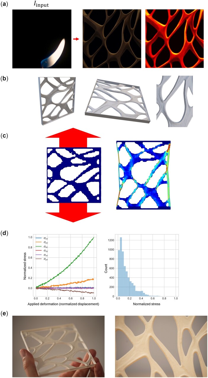
Figure 13.
Entire workflow from design to modeling to manufacturing, for a design based on the intersection of a flame image with a complex text prompt featuring are = ‘a spider web with thick lines on black background’ and = ‘the internal details of wood microstructure’. Other constant parameters . (a) Overview of the design steps from raw image to symmetrically extruded 3D material with a box added at the exterior as shown in (b) (we follow the same process of symmetrically extruding the image based on pixel intensity as explained in Fig. 12). Panel (c) shows a simple mechanical assessment under tensile deformation and (d) shows the resulting stress–strain results and stress field statistics for the Von Mises stress. (e) Photographs of the final manufactured material using FDM 3D printing. Supplementary Movie M4 depicts the stress field as the sample is deformed. Supplementary Movie M6 shows a recording of the additive manufacturing process for this and some of other samples reported in this article.

