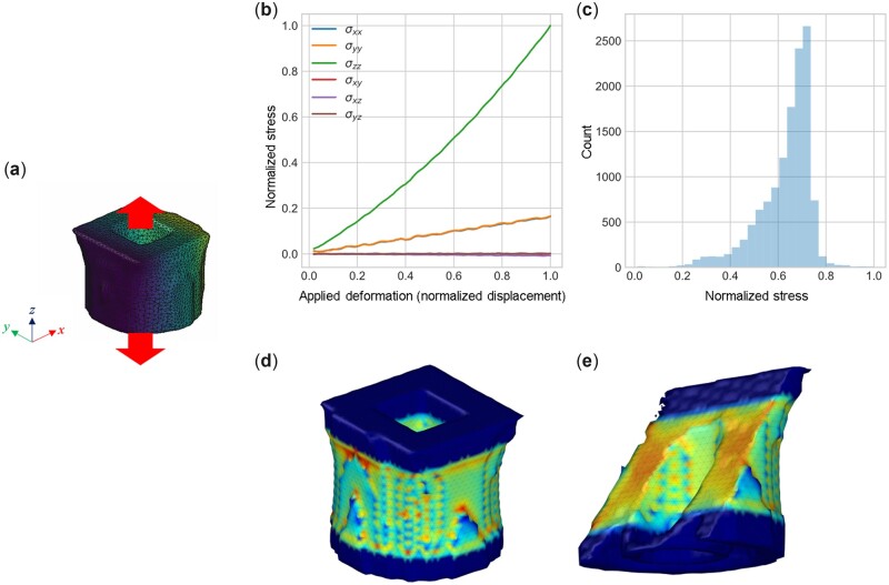
Figure 7.
Mechanical assessment of one of the designs shown in Fig. 5. We limit the exploration to a simple tensile test (a), resulting in stress–strain curves (b), a depiction of the Von Mises stress (c), and a stress field in the 3D domain (d) and a cross-section (e). All stresses and displacements are plotted in non-dimensional units, normalized by the largest stress/displacement in the numerical experiment.

