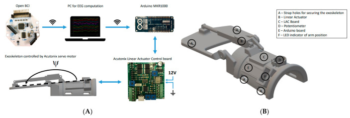
Figure 12.
(A) The hardware setup. The Arduino control board and Linear Actuator were mounted on the exoskeleton. The signals were transferred to the OpenViBE PC running OpenViBE via a wireless connection. When an imagined wrist extension was identified, a trigger was transmitted to the Arduino on the exoskeleton through wireless communication. A wire linked the Arduino to the Linear Actuator Control board. A 12 V power supply was used to power the Linear Actuator Control board. A wire linked the motor to the Linear Actuator Control board. (B) The 3D-printed exoskeleton. The contact surfaces of the forearm were padded with foam to improve comfort. Velcro straps were used to fix the exoskeleton to the subject’s forearm [102].

