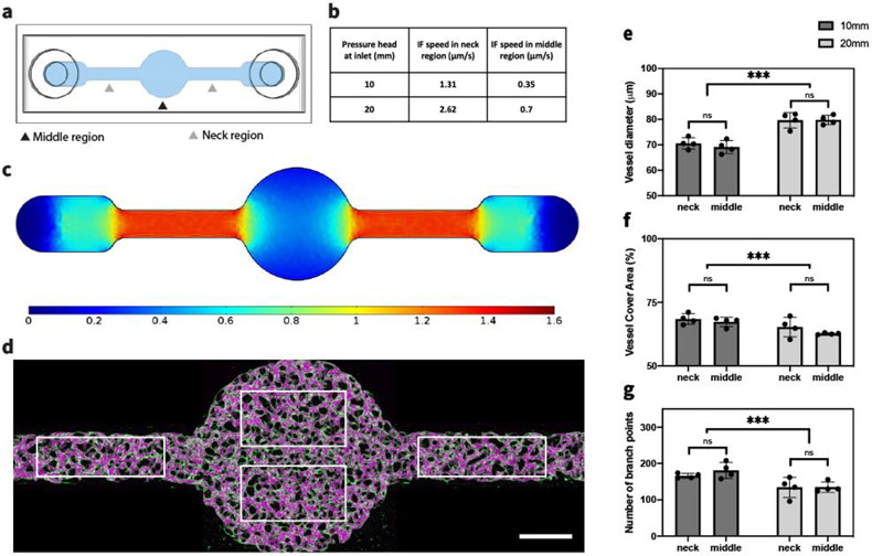
Figure 3.
IF affects global MVNs structures. (a) Schematic of modified single channel device used to generate an inhomogenous IF. (b) Average IF speed in neck or middle ROIs of modified single channel device with corresponding pressure differences, calculated in COMSOL. (c) Profile of IF speed induced by 10 mm H2O pressure difference, calculated in COMSOL. (d) MVN formed under 10 mm H2O pressure difference. White rectangles indicate ROIs of neck and middle regions for statistical analysis. Scale bar is 1 mm. (e-g) Statistical analysis of morphological parameters of MVNs in middle or neck regions of modified single channel device under 10 mm or 20 mm H2O pressure difference. n=2 devices for each IF condition, 4 ROIs in each device (2 in the neck regions and 2 in the middle region, as shown in (d)). Significance was determined with t-tests. ***P < 0.01.

