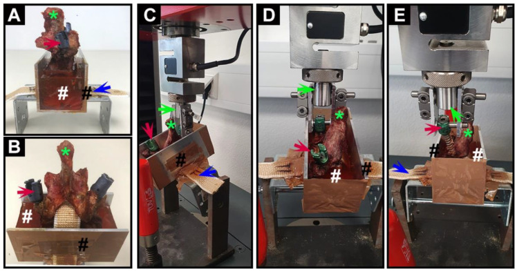
Figure 2.
Photographs of vertebra fixation and biomechanical testing process. (A) Lateral view and (B) anterior view of a vertebra (*) fixed in the customized metal container (black #) filled with epoxy resin (white #); (C) lateral view; and (D) anterior view of the mechanical testing process of pedicle screws; and (E) the picture of pedicle screws being successfully pulled out from the vertebra. Red arrows indicate the pedicle screws; blue arrows indicate the fixed band; green arrows indicate the piston of the testing machine.

