
Figure 3. Ligand binding to TRPM8MM.
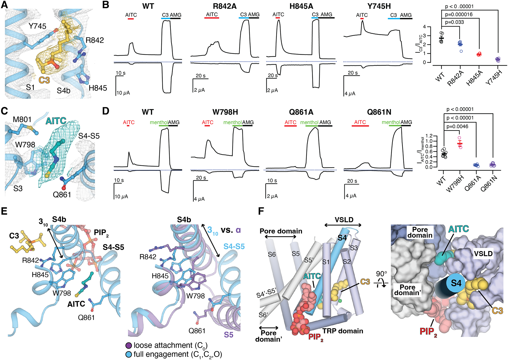
(A and C) EM densities for C3 [(A) yellow] and AITC [(C) teal] in the O state PIP2-C3-AITC-TRPM8MM structure. Ligands and residue sidechains are shown as sticks. Densities are contoured at thresholding 0.11 for C3 [(A) yellow mesh], 0.200 for AITC [(C) teal mesh], and 0.27 for TRPM8MM channel (gray mesh), respectively.
(B and D) Representative TEVC recordings on wildtype and mutant TRPM8MM channels at −60 mV (lower traces) and +60 mV (upper traces). Horizontal colored lines denote the application of 2 mM AITC (red), 300 μM C3 (blue), and 50 μM AMG2850 (AMG) (black). The dotted lines denote the zero current. Summary of the current magnitudes in response to 300 μM C3 relative to 2 mM AITC at +60 mV from experiments in the left panels [(B), rightmost panel] and the current magnitudes in response to 2 mM AITC relative to 1 mM menthol at +60 mV [(D) rightmost panel], respectively. Values for individual oocytes are shown as open circles along with mean ± S.E.M. (n = 3 to 10 oocytes). P-values are calculated by two-tailed Student’s t-test.
(E) Comparison of conformational changes at S4b and S5 upon PIP2, C3, and AITC binding reveals that AITC cannot bind to TRPM8 in the C0 state (right). Ligands and residue sidechains are shown in sticks.
(F) PIP2, C3, and AITC bind surrounding the S4b helix (blue cylinder). TMD helices are shown in either cylinder (left) or surface (right). The neighboring pore domain (indicated by an apostrophe) is colored gray.