
Fig 3.
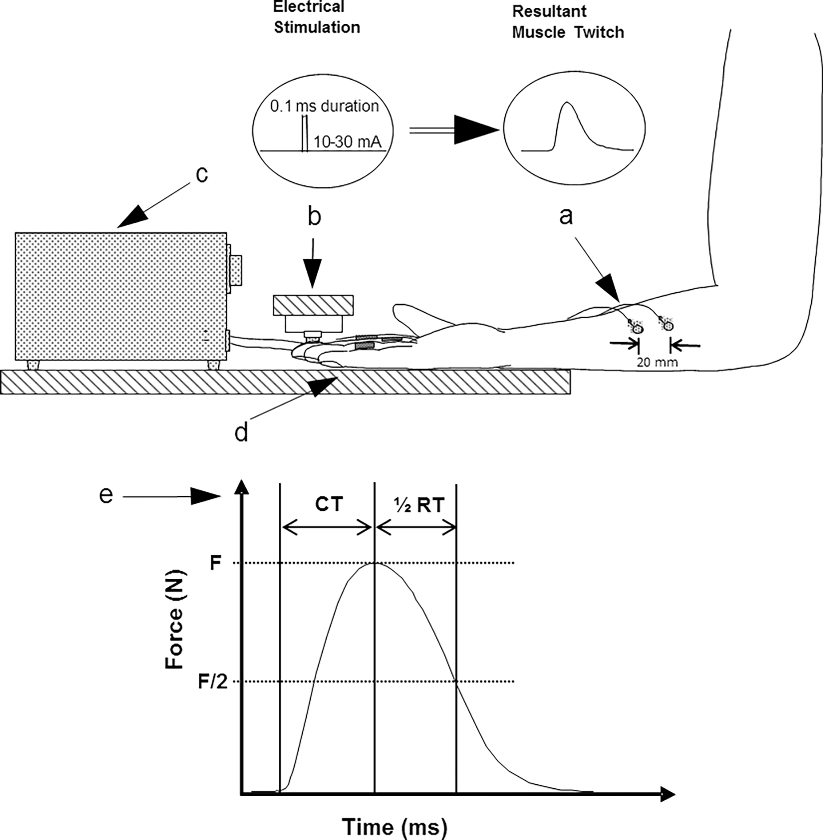
Diagram of the twitch measurement apparatus as seen from the side and twitch force measures: (a) surface electrodes over FDS; (b) force transducer over the middle finger; (c) electrical stimulator; (d) restraining jig; (e) twitch force profile: F (twitch force), CT (contraction time), ½ RT (½ relaxation time), and total contraction duration (CT + ½ RT). Inserts show the electrical stimulation and the resultant muscle twitch