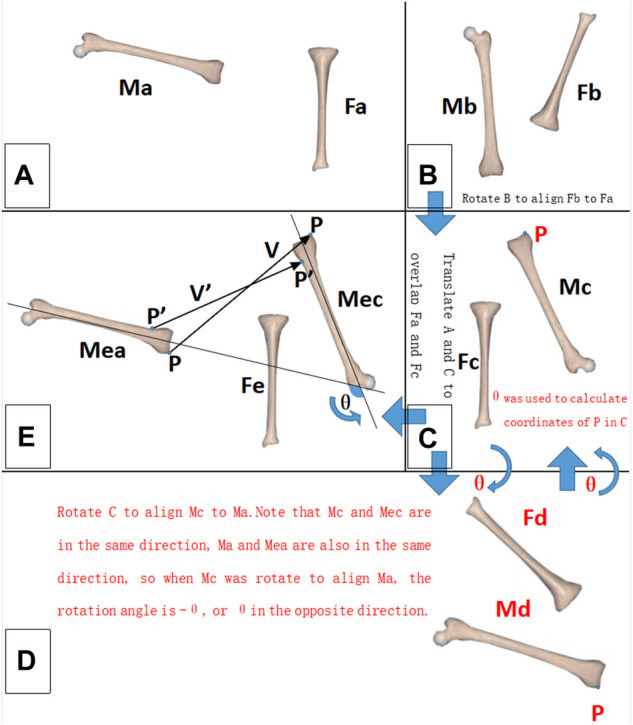
FIGURE 2.

Schematic diagram of the relative motion measurement. For a 2-dimensional rigid body, the black font part should be noted; for a 3-dimensional rigid body, the black and red font parts should be noted. (A) Initial state of the rigid bodies. (B) Terminal state of the rigid bodies. (C–E) Measurement process. M: moving rigid body. F: fixed rigid body. P, P′: reference point. V, V′: displacement vector of the reference point. θ: rotation angle of the moving rigid body (M).
